Introduction to Magnetic Fields
Magnetic Field Basics
This section provides background information on magnetic fields with reference to electron microscopes and similar instruments. Magnetic fields are created by electric currents in the space around where the currents flow. Currents which do not change with time (called direct currents or DC) make constant magnetic fields which we call DC fields. A gradual change in a direct current creates a corresponding gradual change in the DC field. By convention we refer to unchanging fields and fields which change in this slow non-periodic manner as DC fields.
Currents which change sign in a regular manner with time are called alternating currents or AC and give rise to corresponding AC magnetic fields.
The most common AC fields are created by power lines and usually have fundamental frequencies of 50 or 60 Hz (referred to as "line" frequency) often with harmonics up to about 5 kHz. AC fields at other frequencies may be generated by rotating machines containing permanent magnets. Examples are magnetic stirrers and plasma etch machines which may make fields at about 0.3 Hz.
The units used to measure magnetic fields are as follows....
SI unit of magnetic field strength: Amp/metre (A/m)
SI unit of magnetic flux density: Tesla (T)
CGS unit of magnetic flux density: Gauss (G)
The SI units are the modern units but the old CGS unit, the Gauss, is still so widely used that it has been kept in the Spicer Consulting systems. The old CGS unit of magnetic field strength, the Oersted, is now rarely used.
The Amp/metre unit is commonly used by the electricity supply industry as it relates directly to the currents which are generating the magnetic field. The Tesla and Gauss are units of the flux density created by the magnetic field and are the most common units used in measurement of fields. The relationship between the units (in air or space) is as follows...
1 Amp/metre = 1.257 microTesla = 12.57 milliGauss
The Earth's Magnetic Field
The planet earth is surrounded by a DC magnetic field which is created by a direct current flowing in the earth's molten core. The current flow and the magnetic field are sustained by the "dynamo" effect. Magnetic field is a vector quantity, that is, it has a magnitude and a direction. The magnitude of the earth's field is about 0.5 Gauss (50 microTesla). The direction of the magnetic field vector is approximately vertical at the north and south poles and horizontal (pointing north) at the equator.
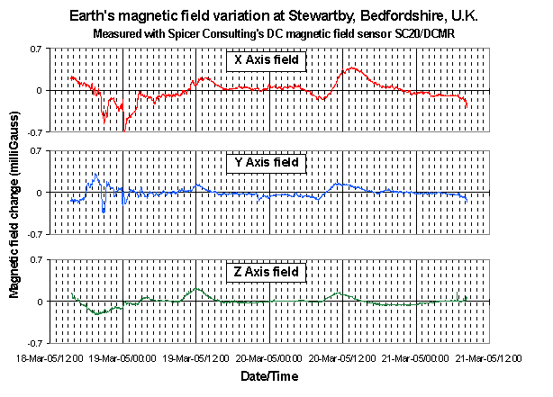
The earth's field undergoes significant changes (including sign reversal) rather randomly on a time scale of thousands of years. There are also small changes of 1 to 5 mG daily which are thought to relate to the solar wind interacting with the earth's ionosphere. The figure below is a chart recording of the changes in the earth's field over a period of three days measured in our Stewartby Lab. using the SC20/DCMR magnetic field sensor. The sensor Y axis is aligned with magnetic north, the X axis points east and the Z axis is vertical.
Electron Microscopes
Electron microscopes control the motion of their electrons using electric and magnetic fields inside the part of the instrument called the "column". Focussed ion beam systems are similar. The column usually comprises a stack of electron optical components, "lenses" to focus the electron beam and "deflectors" to position the beam. The column is mostly made of ferromagnetic iron which serves as the magnetic circuit for the lenses and the mechanical structure of the column. The magnetic fields inside some of the lenses can be as large as 10,000 Gauss (1.0 Tesla) i.e. 20,000 times the earth's field. The iron structure of the column serves as a partial barrier to magnetic fields entering the column from outside and the large internal lens fields leaking out.
Ambient magnetic fields penetrate the electron beam column from outside (to some extent) and add to the magnetic fields in the lenses and deflectors. AC fields, and DC fields which change during operation of the microscope, may degrade the performance of the microscope. Usually, DC fields penetrate the column more than AC fields. This is because AC fields are also attenuated by the mechanism called "eddy current shielding".
Changing DC fields, which cause a problem for electron microscopes, can be created by steel objects moving and locally distorting the earth's field. Examples include cupboard doors, chairs, motor vehicles and elevators (lifts). Large changing DC fields can be created by electric trams and commuter trains which draw direct current from an overhead wire, returning it through the rails. Superconducting magnets in research facilities are also not good news for electron microscopes because they can radiate large DC fields for tens of metres.
The earth's magnetic field also penetrates the electron beam column but, for most electron microscopes, it can be considered constant since it changes slowly compared with the time taken for a micrograph. Its effect is adjusted out with the instrument controls during routine operation of the microscope and the operator is generally unaware of its presence. For electron beam lithography machines used to write reticles for IC chips (or to write directly on a silicon wafer) the changes in the earth's magnetic field during the write time (several hours) may significantly degrade the accuracy of the written pattern. Some EBeam lithography machine manufacturers are now specifying maximum field changes of 0.1 mG. Since the earth's field changes much more than this on a typical day, magnetic field cancelling would be necessary for these machines to meet specification.
Electron microscopes form their image either by projection (TEMs) or by scanning to form a TV like image (SEMs, STEMs). The effect of DC or AC fields on projected images is to move the whole image and the result is loss of resolution on the image screen. The effect of DC or AC fields on scanned images is to move parts of the image. AC line fields typically produce wiggly edges on the image often called "edge tearing" or "ragging". DC fields may cause discontinuities in the image and cause straight edges to look like mountain ranges. Some microscope manufacturers design their scanning sytems to operate synchronously with the 50 or 60 Hz line. This removes the edge tearing caused by the AC line fields but introduces distortion into the image (e.g. the image of a square grid is bent). However, distortion is generally less visible than edge tearing and may be acceptable for some applications.