

Magnetic Field due to a Moving Gas Cylinder
How it affects a TEM and what to do about it
We were asked whether moving gas cylinders on the floor above a large TEM would cause a problem with its magnetic field environment. We made measurements of the DC field fluctuations at different positions as a large gas cylinder was wheeled past on a trolley. The results show that a non-uniform field fluctuation was created by the cylinder, which would exceed the specifications of the microscope. It would require a dual magnetic field cancelling system to bring the field back into specification. It should be noted that the cylinder was a standard type used in many laboratories, but we only made measurements for one cylinder. Other cylinders may give different levels of field.
Introduction
A large high resolution TEM with monochromator and energy analyser can image with sub-Angstrom resolution, but is very sensitive to magnetic fields in the environment. Typically the field is required to be stable to within 30 nT Pk-Pk, but some models have tighter requirements.
We were asked whether moving gas cylinders on the floor above a large TEM would cause a problem with its magnetic field environment, so we decided to make some measurements. It was not convenient to measure the field below the cylinder, so we measured the field above it.
Procedure
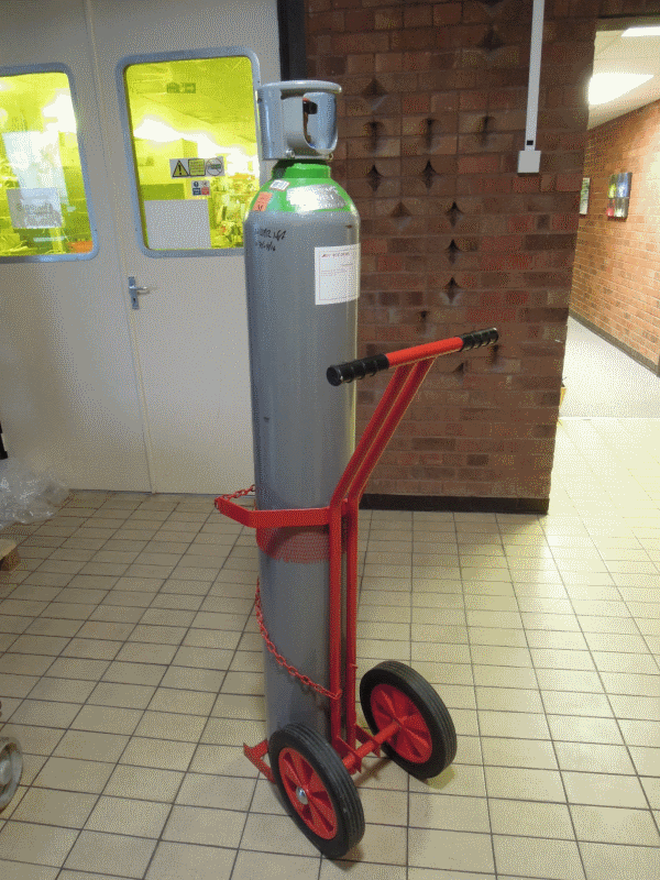
The steel gas cylinder was made to BS 5045-1. It was 1.5m long and 0.22m diameter. It was found to be slightly magnetised, with fields up to about 4 times the Earth’s field on the surface of the cylinder. No special effort was made to magnetise or de-magnetise the cylinder, so it may be regarded as typical. It was placed on a standard steel trolley designed to carry gas cylinders.
A Spicer Consulting 3-axis DC sensor was placed at various different heights. The cylinder trolley was pushed under the sensor for a distance of 5m in the Y direction relative to the sensor. The Earth’s field is X=120, Y= 140, Z=-440 mG, relative to the sensor. The sensor was reset each time to remove the Earth’s field from the measurement.
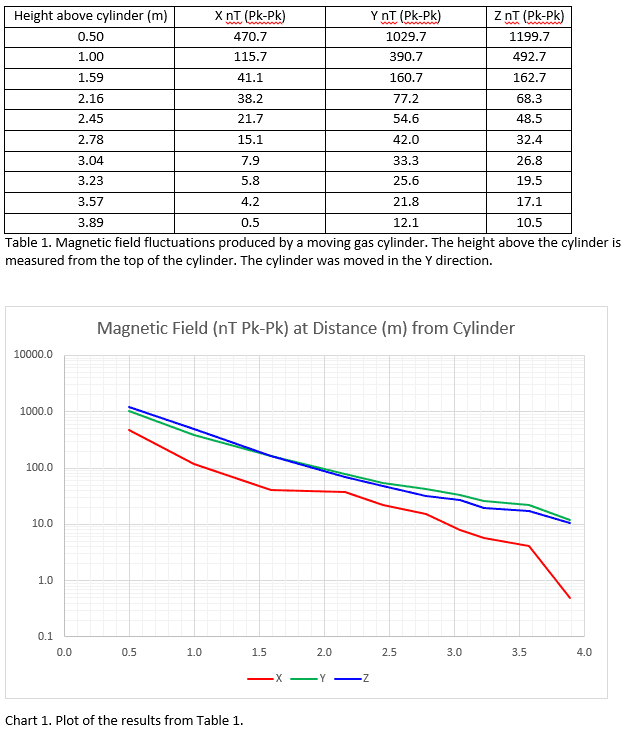
The SC11 Chart Recorder was used to chart the magnetic field waveform in 3 axes. The resulting waveforms were extracted from the chart recorder results and plotted using SCplot. The peak to peak change reported by SCplot was adjusted to remove the AC (50 Hz) that broadens the trace on the chart. The height of the cylinder was subtracted from the height above ground to obtain the distance from the cylinder. The results are summarised in Table 1 and Chart 1 below.
Results
Discussion
It should be pointed out these results apply to a particular gas cylinder at a particular location. Other cylinders may be different in size and differently magnetised. Part of the field change recorded is due to distortion of the Earth’s field. The steel in the cylinder has a high permeability, so magnetic field flux lines are attracted to run along the cylinder rather than through the air next to it. Therefore the direction of the Earth’s field affects the field changes made by the cylinder. We have not attempted to quantify the range of fields that different cylinders might make in different locations. We present these results as what they are. Some general conclusions can be drawn, even if the actual field levels are twice or half these results.
The results show that the Y and Z fields were much larger than the X field. Some errors in the smaller X field were introduced by vehicles moving past in the road outside. The overall trend is clear: The cylinder makes a non-uniform change in DC field level as it is wheeled past. At 0.5m from the cylinder it is over 1000 nT Pk-Pk and at 4m it is down to 10 nT Pk-Pk.
Now let us estimate the effect of wheeling a cylinder in the room above, directly over a TEM. Assume that the TEM electron gun is at 2.8m and GIF is at 0.5m. Assume that the TEM room is 4m high with a ceiling 0.3m thick. The cylinder is at 4.3m height and is 1.5m from the gun and 3.8m from the GIF. It would make about 200 nT Pk-Pk at the gun and about 12 nT Pk-Pk at the GIF. This is outside the specifications of the TEM at the gun. It may be outside the spec at the GIF, depending on the type of TEM.
Fields of this level can be cancelled using a Spicer Consulting SC24 Magnetic Field Cancelling System. However, the non-uniformity of the field is a concern. If a single SC24 system is installed in the TEM room, a substantially uniform cancelling field can be produced. When cancelling is turned on, this uniform field is superimposed on the ambient field. If the sensor is at mid-height of the TEM, the result will be good cancelling at the sensor, but over-cancelling at the GIF and under-cancelling at the gun. The Magnetic fields at the TEM will not be in specification.
A dual magnetic field system can cancel this. It has one system installed in the upper half of the TEM room and another installed in the lower half. The upper system cancels the field at the gun and the lower system cancels the field at the GIF. The overall cancelling field varies along the column between the two values, roughly matching the shape of the cylinder field and giving good cancelling all along the column.